SVG and file preparation

Nesting compares the usable sheet area, margins and gaps with the actual shapes being produced.
A design can fit inside a sheet on screen and still waste material or cause production problems. Parts may be spread too far apart, placed beyond a safe edge margin, rotated against the grain, or arranged so that cutting heat and tool movement create issues. Small gaps may also disappear during cutting, while a damaged sheet edge can ruin an otherwise careful layout.
Nesting is the process of arranging parts on a sheet so they use the available material efficiently. Good nesting balances low waste with safe spacing, correct orientation, easy handling and reliable production. The goal is not simply to squeeze every shape into the smallest possible area. A practical layout leaves enough room for the machine, the material and the person handling the finished parts.
Who benefits from nesting?
Nesting is useful for anyone cutting multiple SVG parts from plywood, acrylic, MDF, card, vinyl or similar sheet materials. It can help when making signs, ornaments, product components, packaging, templates, furniture parts or repeated decorative designs.
Manual nesting is often enough when a sheet contains only a few large parts, when the shapes are visually simple, or when orientation matters more than maximum material use. It also works well when you already know the material’s grain, damaged edges and other limitations.
A layout or nesting tool becomes more useful when a job contains many different shapes, repeated quantities or irregular contours. Automated tools can quickly test arrangements that would take a long time to find by hand. However, an automatically generated layout still needs human review. Software may not understand a visible front surface, a fragile edge, a preferred grain direction or a production rule that is obvious to you.
Prepare before arranging parts
Start with the final SVG whenever possible. Last-minute edits to dimensions, duplicated parts or hole positions can invalidate the layout. Confirm that the file contains the correct quantities and that parts are not accidentally duplicated, hidden or combined in a way that changes the intended output.
Record the usable sheet size, not just the advertised sheet size. A sheet may have a rough, damaged or uneven edge. Protective film, labels or a section with scratches may also reduce the area you actually want to use.
Before placing parts, identify:
- the sheet width and height;
- unusable or damaged edges;
- the required outer margin;
- the minimum gap between parts;
- the material grain or visible direction;
- which parts may be rotated;
- which parts must remain mirrored or matched;
- the machine’s working-area and movement limits;
- whether protective film should remain on the material;
- whether a small test piece is needed first.
A test piece is especially useful when the material, finish or cutting process is unfamiliar. It can reveal how the material behaves, whether narrow bridges remain intact and whether your planned spacing is practical.
A universal method for nesting SVG parts
1. Decide the usable sheet area
Begin by defining the area that is genuinely available for production. If the sheet has a damaged edge, exclude it. If clamps, hold-downs or machine limits affect the perimeter, exclude those areas as well.
Do not treat nominal sheet dimensions as a promise that every millimetre can be used. A smaller, clearly defined usable area is easier to inspect and less likely to create surprises.
2. Set an outer safety margin
Leave a margin between the parts and the sheet edge. The correct amount depends on the material, machine, workholding method and production workflow, so there is no universal value.
The outer margin protects against uneven edges and positioning errors. It can also make it easier to handle the sheet without damaging a part near the perimeter. If one side of the sheet is more vulnerable or has a visible defect, use a larger margin there or exclude that edge completely.
3. Set a gap between parts
Decide how much space must remain between neighbouring parts. This gap can affect whether adjacent cuts merge, whether small sections remain attached, and whether a tool or cutting process can follow the intended paths.
Use a consistent starting gap, then increase it where parts have delicate tips, narrow bridges or heat-sensitive details. The required spacing may also change when different operations are performed on the same sheet.
The visible outline may not show every production concern. A stroke, offset, kerf or tool diameter can affect the actual result. Check how your workflow interprets the SVG before relying on a very tight layout.
4. Group similar parts and quantities
Place repeated parts together or in an organised pattern. Grouping makes it easier to count them, spot missing pieces and identify whether the layout contains the correct quantity.
Similar parts can often be arranged efficiently because their shapes and dimensions are compatible. Keep matched sets together when that helps with assembly. Place large or orientation-sensitive pieces first, then fill the remaining spaces with smaller parts.
5. Allow rotation only where it is safe
Rotation can reduce waste, but it is not automatically allowed for every part. Consider the material and the purpose of the piece before turning it.
Wood grain, brushed acrylic, printed surfaces and other visible directions may need to run consistently. Text, arrows, logos and directional artwork may become incorrect when rotated. Some components are intentionally mirrored, while others must remain in a particular orientation to match another part.
Protective film can also have a preferred side or direction. If the sheet has a front surface, inspect how the finished piece will look rather than judging the layout only from the outline.
6. Inspect the layout visually
Zoom out and inspect the full sheet, then zoom in on the tightest areas. Look for parts that are too close to one another, narrow gaps, accidental overlaps, reversed text, missing quantities and pieces placed near a damaged edge.
Check the negative spaces as carefully as the parts themselves. Empty areas may reveal that a group can be shifted, rotated or reorganised. Do not fill every empty space automatically: a gap may be necessary for safe processing, handling or separation.
7. Run a small real-material test
Before committing the entire sheet, test a representative part or small group on the actual material. A test can reveal differences between the screen and the physical result, including edge quality, melting, scorching, tool access, film behaviour and the strength of small details.
The test does not prove that every part of the full layout will behave identically. It gives you evidence before you use the whole sheet. If a gap is too narrow or a detail too fragile, revise the layout before production.
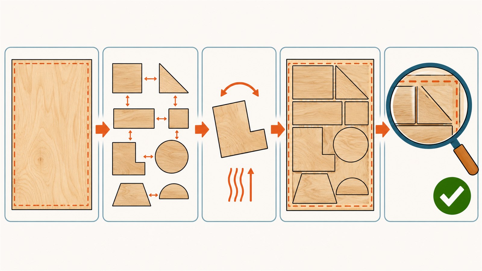
A practical nesting workflow defines the usable area first, then checks spacing, orientation and a physical test.
Why direction and condition matter
Material direction is one of the main reasons a mathematically compact layout may not be practical. Plywood and other sheet materials can have a visible grain or structural direction. Rotating one part may make its appearance inconsistent with the rest of a product.
The front and back surfaces can matter too. A decorative finish, coated face or protective film may need to remain on a specific side. Text and graphics are obvious examples of content that can become wrong when rotated or mirrored, but less obvious directional details can matter as well.
Matched parts require special attention. A left and right component may need to be mirrored, while two parts that look similar may not be interchangeable. Do not assume that flipping or rotating a shape creates a valid replacement.
Finally, inspect the physical sheet. A damaged edge, bowed section, scratch, label or uneven corner can limit where parts should go. Good nesting begins with the material you actually have, not an ideal rectangle.
Bounding-box layout versus contour-aware nesting
A fast way to arrange parts is to use their rectangular bounding boxes. A bounding box is the smallest rectangle that contains a shape. This approach is simple and quick, and it works well for parts that are already close to rectangular or when speed and clarity matter more than maximum utilisation.
The disadvantage is that empty corners of each rectangle may remain unused. Irregular parts can therefore produce more waste than necessary.
Contour-aware nesting considers the actual outer shape of each part rather than only its enclosing rectangle. It may place curves, angled edges and irregular outlines closer together. This can improve material use, especially when a sheet contains many complex parts.
More precise nesting is not always the best choice. It can take longer to calculate, be harder to inspect and leave less room for practical handling. A tightly packed layout may also be less forgiving if the material shifts or if one part needs to be removed and re-cut. Choose the level of precision that fits the job, then verify the result against real production requirements.
Common layout problems
| Common layout problem | Likely cause | Practical check |
|---|---|---|
| Parts fit on screen but fail near the edge | No usable-area or edge-margin allowance | Mark damaged and restricted edges before placing parts |
| Several parts are too close together | Spacing was judged visually or inconsistently | Zoom in and check the narrowest gaps |
| Finished pieces have the wrong appearance | Parts were rotated or mirrored without checking direction | Review grain, front surface, text and matched parts |
| The sheet contains the wrong number of pieces | Duplicates or missing quantities in the source file | Count groups before and after nesting |
| A compact layout is difficult to separate | Parts were packed too tightly for the workflow | Review gaps, handling space and the test piece |
| Automatic nesting looks efficient but is unusable | The tool did not know material or production constraints | Inspect orientation, margins, film and damaged areas |
Reviewing an automatically generated layout
Treat an automatic layout as a draft, not a final decision. Confirm that every required part appears and that no extra or hidden objects have been included.
Check the outer boundary, the chosen edge margin and the smallest gaps, especially around narrow points, holes, corners and delicate features.
Next, verify orientation. Look for rotated text, inconsistent grain direction, mismatched left and right parts, and front surfaces that have been turned incorrectly. Check whether the software has placed parts into internal openings. Such arrangements may be valid in some workflows, but they can also create confusion or production errors. Do not assume that every hole is safe space for another part.
Finally, look at the layout as a person preparing and separating the job. Can you identify the parts easily? Can you remove them without damaging neighbouring pieces? Would a slightly less compact arrangement make inspection or handling safer? If so, the extra material may be worthwhile.
Frequently asked questions
What does nesting mean in SVG production?
Nesting means arranging multiple parts on a sheet so they use material efficiently while respecting margins, gaps, orientation and production constraints.
Is manual nesting good enough for a small project?
Often, yes. Manual nesting is practical when there are only a few parts, the shapes are simple or material direction is important. It becomes slower and more error-prone as the number of parts increases.
Should every SVG part be rotated to save material?
No. Rotation may be restricted by grain, visible surfaces, text, graphics, matched parts or the intended assembly. Rotate only parts that remain valid in their new orientation.
How much space should I leave between parts?
There is no universal spacing value. It depends on the material, machine, process, tool or beam characteristics and the way parts will be separated. Confirm it with your workflow and a real-material test.
Is contour-aware nesting always better than bounding-box nesting?
No. Contour-aware nesting can reduce unused space around irregular shapes, while bounding-box nesting is faster and often easier to inspect. The better method depends on the job.
Can I place one part inside the hole of another?
Only if your complete workflow supports it and the inner part has enough clearance, correct orientation and safe separation. A hole that looks like free space may create production errors.
How do I know whether an automatic layout is ready?
Check the part count, sheet boundary, edge margin, gaps, orientation, material direction, damaged areas and handling requirements. Then test a representative section on the actual material.
Conclusion
Efficient nesting is a balance between saving material and keeping the job reliable. Define the usable sheet area, set practical margins and gaps, group parts carefully, restrict rotation where necessary and inspect the tightest areas before production.
Your next step is to take one real SVG job, mark the usable sheet boundary and place the largest orientation-sensitive parts first. Fill the remaining space, review the layout manually and run a small test before committing the full sheet.
Keep learning
Choose another practical guide or return to the tools for the next step.